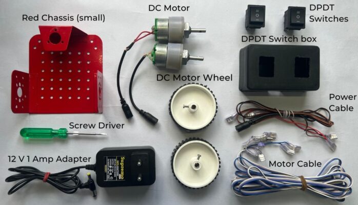
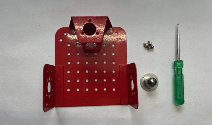
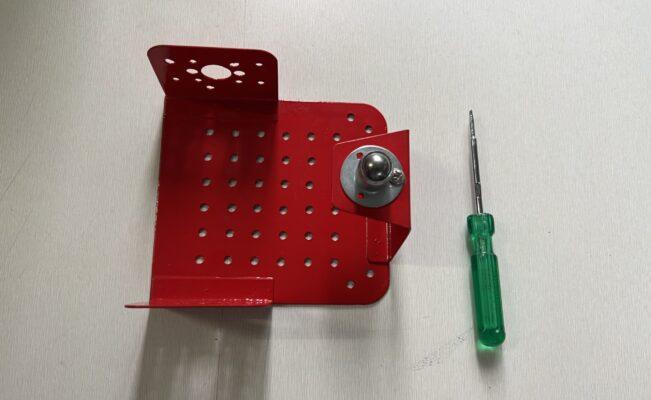
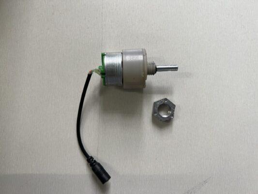
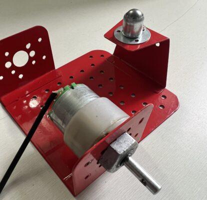
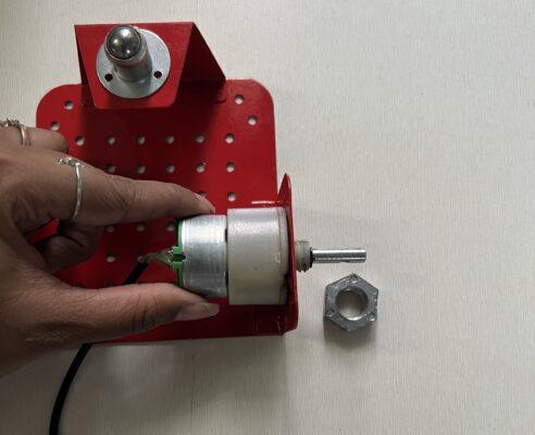
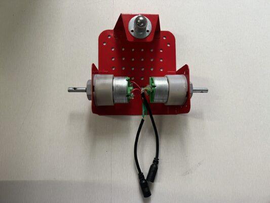
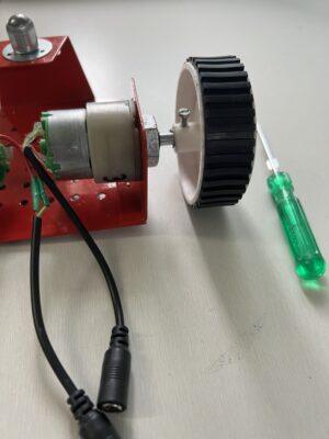
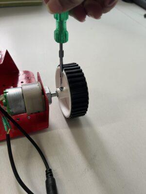
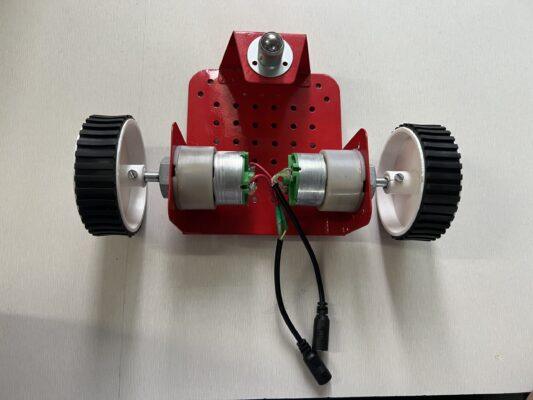
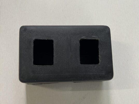
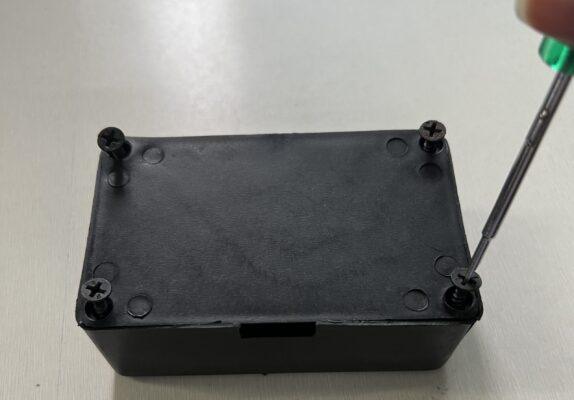
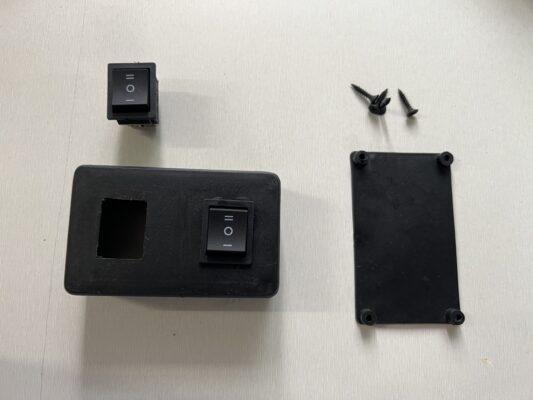
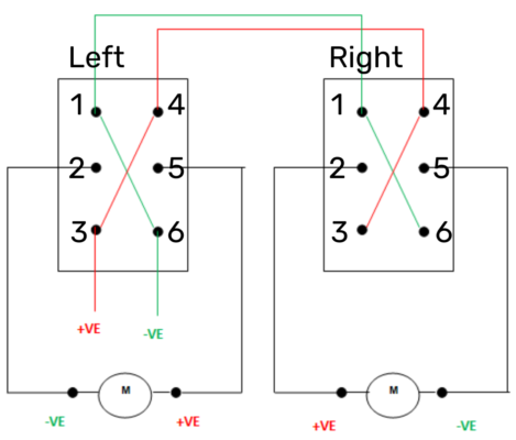
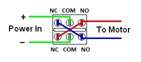
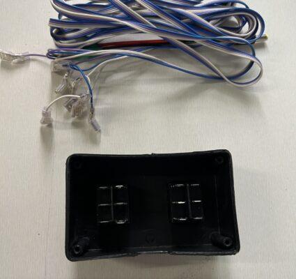
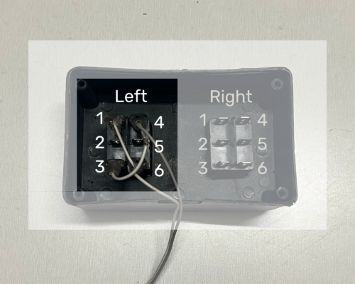
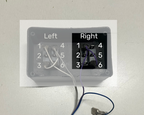
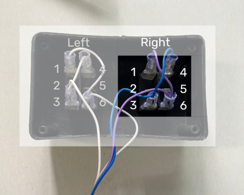
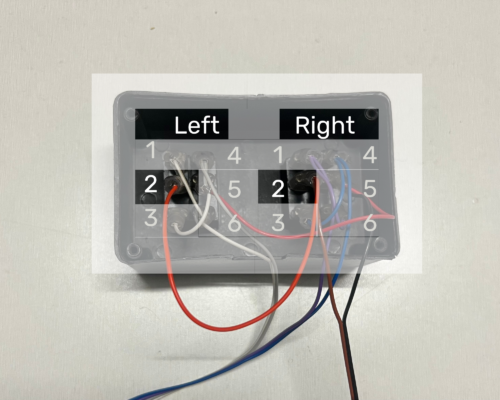
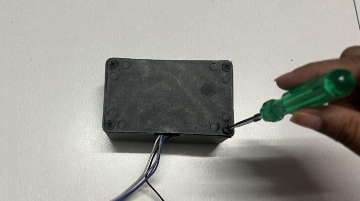
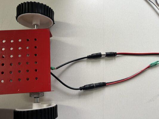
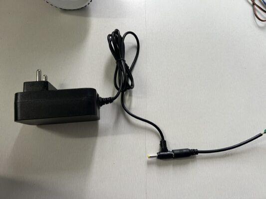
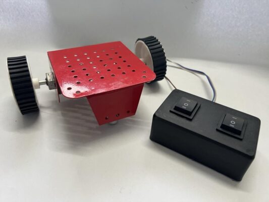
Manual Robot Leave a Comment / Electronics Product Engineering / By Manish Maurya Manual Robot Kit Click here Red Chassis (small)150 RPM DC MotorCastor wheelWheel 70 x 20 mm DC MotorDPDT switchDPDT Switch Box12V 1 Amp AdapterMotor CablePower CableScrew driverScrews Step 1: Take the red chassis and screw the castor wheel at the bottom. Step 2: Unscrew the nut from the motor and place it through the hole present on the side and screw the nut in order to secure the motor in place. Step3: Similarly place the other motor in the other hole, tighten the nut to secure the motor in place. Step 4: Place the wheel on the shaft of the motor and secure the wheel in position with the help of a screw. Step 5: Attach the other wheel in the same manner. Step 6: Take a DPDT Switch box, unscrew the base of the box and place the DPDT switches in place. Step 7: Connect the motor cable and the power cable to the switches. As shown in the circuit diagram and images. Step 8: Screw the base back in place. Step 9: Now connect the male DC jack coming out from the controller to the female DC jack attached to the motor. Step 10: Connect the female DC jack from the controller to the 12 V adapter and plug it into the power supply. Step11: Your robot is ready Click here Manual Robot Kit Click here Red Chassis (small)150 RPM DC MotorCastor wheelWheel 70 x 20 mm DC MotorDPDT switchDPDT Switch Box12V 1 Amp AdapterMotor CablePower CableScrew driverScrews Step 1: Take the red chassis and screw the castor wheel at the bottom. Step 2: Unscrew the nut from the motor and place it through the hole present on the side and screw the nut in order to secure the motor in place. Step 3: Similarly place the other motor in the other hole, and tighten the nut to secure the motor in place. Step 4: Place the wheel on the shaft of the motor and secure the wheel in position with the help of a screw. Step 5: Attach the other wheel in the same manner. Step 6: Take a DPDT Switch box, unscrew the base of the box and place the DPDT switches in place. Step 7: Connect the motor cable and the power cable to the switches. As shown in the circuit diagram and images. Step 8: Screw the base back in place. Step 9: Now connect the male DC jack coming out from the controller to the female DC jack attached to the motor. Step 10: Connect the female DC jack from the controller to the 12 V adapter and plug it into the power supply. Step 11: Your robot is ready